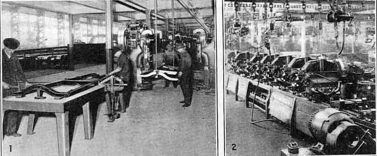
| 1. Place frame assembly on stand. Assemble brake equalizer operating shaft and bushing Assembly in place with two equalizer operating shaft pin caps and two brake operating shaft pin caps, four bolts, four nuts and four cotter pins. Tighten nuts with electric drill. Use grease on all working joints.
|
|
|
2. Move assembly to next stand. Assemble two running boards to frame bracket (front), one right and left running board to frame bracket (rear) with twelve rivets. Rivet, using bar and hammer to hold in place for press operation.
|
|
3. Place in machine and rivet twelve rivets, one rivet at a time.
|
|
4. Place assembly on sliding stand, bottom side up. Assemble right and left hand brake cross shaft assembly; brake equalizer beam with two brake cross shaft frame brackets, two brake cross shaft frame bracket shims, four bolts, nuts
and cotter pins. Tighten nuts. Use grease on working joints.
|
|
5. Assemble two brake rod springs to brake rod spring bracket with four bolts, nuts and lock washers. Tighten two bolts and two nuts, only.
|
|
6. Assemble two engine rear support brackets to frame with two engine rear support cushions (inner), six engine rear support spacers, two engine rear support cushions (outer), two engine rear support plates, six bolts, nuts and cotter pins. Screw nuts on loosely.
|
|
7. Assemble two shock absorber assemblies; front right and rear left. Two shock absorber assemblies; front left and rear right. Attached with two arms, two arms to frame assembly with eight bolts, washers and nuts, and tighten. Set dial of shock absorber on No. 3 for front, No. 4 for rear. Frame bottom side up on conveyor.
|
|
8. Assemble two front fender brackets in place, with two long bolts, short bolts, four nuts and four cotter pins.
|
|
9. This operation done on special fixture before assembly to chassis. Assemble front spring assembly to front axle, tie rod and radius rod assembly, with two front spring hangers and front spring bolts, four nuts and cotter pins. Press four lubricator fittings in place. Line front spindles to fixture, and tighten tie bolts and nuts of tie rod. Assemble two front hub dust caps in place on spindle with hammer and punch. Tighten front spring hanger bolts on stand, so front radius rod is in air. Assemble drag link with two drag link ball seats, plugs, springs, cotter pins, grease retainers and grease retainer caps to steering gear arm, assemble to spindle arm and tighten. Use grease on all moving joints.
|
|
9 1/2. Place assembly on sliding conveyor sidewise. Assemble front axle assembly, front spring assembly and drag link to front end of chassis with front spring clip bar, two front spring clips, one starring crank bearing, four nuts and cotter pins. Tighten nuts. Use grease before placing spring in front crossmember. Use conveyor to bring spring and front axle assembly to conveyor line. This operation to be done bottom side up.
|
|
10. Assemble to rear end of frame, rear spring assembly with two rear spring clips, rear spring clip bars, four nuts and cotter pins, and tighten. Use grease before placing springs in rear crossmember. This operation to be done bottom side up.
|
|
11. Assemble rear axle assembly to spring frame assembly with two rear spring hangers and rear spring hanger bars, four nuts and cotter pins. Place four lubricator fittings in hangers. Frame bottom side up on conveyor.
|
|
12. Connect universal housing cap outer assembly to brake cross shaft assembly, right and left hand, with two bolts, nuts and lock washers, and tighten. Use grease on torque tube bell. Frame bottom side up on conveyor.
|
|
13. Hang on overhead conveyor, bottom side up. Spray with black proxylin all over bottom side.
|
|
14. Remove from overhead conveyor and place on automatic rolling conveyor, sidewise. Spray with black proxylin all over top side.
|
|
15. Assemble two front brake housing and brake shoe assemblies to front axle with two pins, felt washers, grease baffle assemblies, eight bolts, nuts and
cotter pins. Tighten nuts. Place two front wheel bearing cone assemblies, two grease retainer washers. Dope all front end grease cups.
|
|
16. Assemble right and left hand engine pan to side members of frame assembly, only, with six bolts, nuts and cotter pins. Tighten with Yankee screw driver.
|
|
17. Clean spot on center crossmember with gasoline to assemble battery to ground connector assembly with bolt, nut and lock washer, and tighten.
|
|
18. Assemble brake pedal equalizer shaft rod assembly to left hand brake cross shaft assembly with cadmium pin and cotter pin.
|
|
19. Assemble right and left rear brake shoe and housing assembly with two rear brake grease baffle assemblies. Tighten all nuts.
|
|
20. Fill rear axle differential with one quart rear axle oil.
|
|
21. Assemble two bearings, retainers and retainer rings. This operation to be done on hand arbor press before placing on assembly.
|
|
22. Remove axle nuts and assemble two rear hub and brake drum assemblies to rear axle.
|
|
23. Remove axle nuts, outer bearing and retainer washer. Assemble two front hub and brake drum assemblies, filled with grease, to front axle. Reassemble bearings and nuts.
|
|
24. Inspection of chassis.
|
|
25. Assemble clamp to hold torque tube bell in place for assembly of engine assembly.
|
|
26. Hang on overhead conveyor, and place on sliding automatic conveyor, with both axles resting on conveyor.
|
|
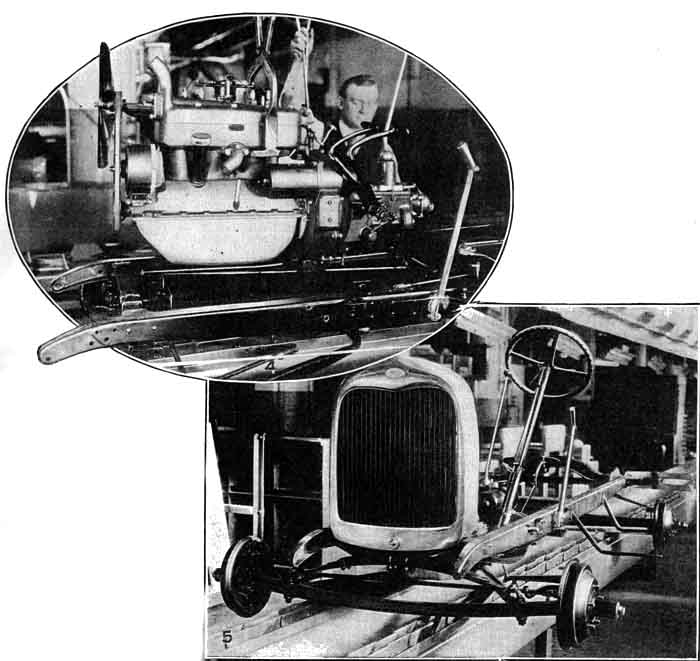
27. Hang engine assembly on overhead conveyor, place in chassis and prop in place. Stamp motor number on left side member near clutch pedal.
|
|
28. Assemble right and left engine pans to oil pan boss and front crossmember with two bolts, nuts and cotter pins.
|
|
29. Touch up with paint wherever necessary. Use quick drying paint.
|
|
30. Assemble front radius rod ball to engine clutch housing with front radius rod ball cap, and two front radius rod ball cap bolt sleeves, springs, nuts, bolts, cotter pins and one retaining pin and retaining cotter pin. Tighten with hand socket wrench.
|
|
31. Tighten front and rear axle shaft nuts with four cotter pins in place.
|
|
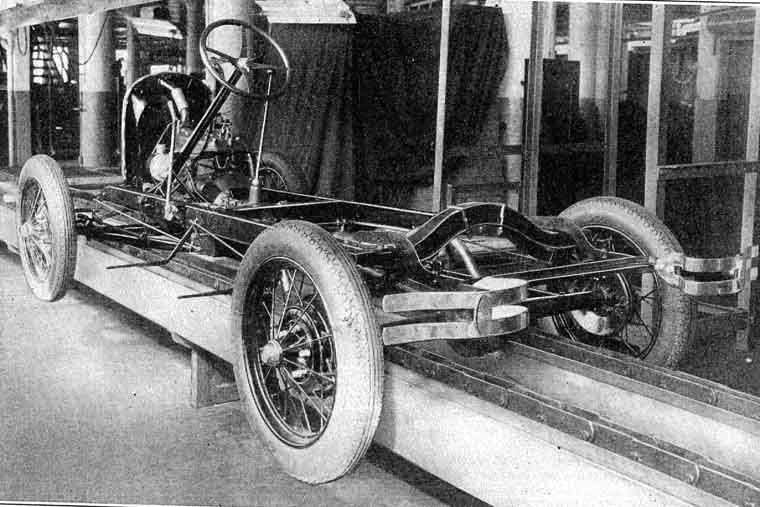
32. Assemble four wheel and rubber tire assemblies to hub and brake drum assembly with twenty nuts, and tighten. Use electric socket wrench. Use grease on bolt threads. Assemble four hub caps in place with punch and hammer.
|
|
33. Assemble four shock absorber link tubes to shock absorber assembly and connect with four filler plugs, lubricator fittings, cotter pins, spring spacers, grease retainers, grease retainer cups and plugs, and tighten.
|
|
34. Assemble four bracket bolts to engine with four nuts and washers, and tighten. Use socket wrench. Assemble two front crossmember bolts to engine with two nuts and washers, and tighten.
|
|
35. Tighten six nuts of engine rear support bracket on frame,
with six cotter pins. Use electric socket wrench.
|
|
|
36. Assembly of radiator before assembly to motor and frame assembly on line. Assemble radiator (less shell) with fan housing assembly, two screws and nuts, one radiator pipe assembly and hose connections, two hose connections and hose clip assemblies, and four hose clip assemblies.
|
|
37. Assemble above assembly to engine and frame assembly on line, with two pads, bolts, springs, and cotter pins. Use gage to set radiator in place.
|
|
38. Assemble front bumper assembly to front end of frame with four bolts, nuts and washers, and tighten.
|
|
39. Assemble four cross shafts to axle brake devises with two brake rod devises, eight brake rod clevis pins and cotter pins, two brake rod spring cotter pins, bolts, nuts and washers, and tighten.
|
|
40. Assemble hand brake lever bracket assembly to frame with hand brake lever arm attached, four bolts, washers and one spring. Tighten.
|
|
41. Assembly of steering gear to wheel and wire assembly before assembling to frame. Assemble to steering gear housing and column assembly, Lighting switch assembly, wheel assembly and assembly of switch, with two conduits, on, conduit for horn, two insulators, four terminals, four screws, spider, two springs, one horse shoe spider retainer.
|
|
42. Assemble above assembly (operation 41) to left side of frame assembly with two bolts and nuts. Tighten.
|
|
43. Assemble muffler assembly to engine exhaust and side frame with muffler pipe bracket, bolt, nut, cotter pin, and tighten.
|
|
44. Assemble battery support assembly to side and center member with four bolts and nuts, and tighten.
|
|
45. Assemble rear bumper assembly to rear end of frame with four bolts, lock washers and nuts, and two bolts, nuts and washers, and tighten.
|
|
|
46. Grease all lubricator fittings with Alemite Air Line Lubri gun.
|
|
47. Fill radiator with water. Assemble radiator shell to radiator with one cap, four screws, washers and nuts.
|
|
48. Assemble battery (with cover in place) with two battery clamps, and nuts. Connect terminals in place.
|
|
49. Assembly of right and left fenders to right and left running board shields with two gimp strips, twenty six washers, fourteen lock washers, fourteen bolts and nuts. This operation to be done on felt padded bench. Use overhead conveyor. Socket wrench.
|
|
50. Assemble above assembly (operation 49.) to chassis with two cloth ribbon strips.
|
|
51. Assemble running board assemblies to fender shields and brackets with two strips of tape for shield edge, eight bolts, ten nuts and two lock washers, and tighten.
|
|
52. Assemble two head lamp assemblies with horn assembly in place, headlamp support and tie rod assembly.
|
 |
|
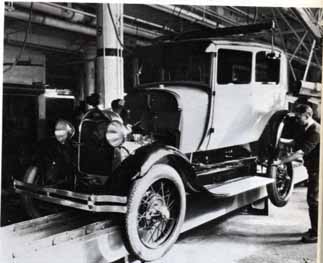
53. Assembly of Tudor body assembly with rear fenders, right and left hand and wheel carrier assembly, tail light and license bracket assembly.
|
|
54. Hang above assembly on overhead conveyor. Place on chassis in place.
|
|
55. Assemble to chassis and engine assembly with eight bolts, eight lock washers, eight nuts, four blocks and rubber assemblies.
|
|
56. Assemble four bolts to rear bumper to frame, four lock washers, four nuts, tighten.
|
|
57. Assemble two blocks with rubber attached to running board shield and frame
|
|
58. Assemble two radiator rods to radiator and body with six nuts, two cup washers, four washers.
|
|
59. Assemble right and left hand shelf assembly to frame with eight screws, lock washers and nuts, and tighten.
|
|
59 1/2. Assemble two hood clip assemblies with two blocks, screws and nuts.
|
|
59 3/4. Assemble hood clip bumper.
|
|
60. Assemble front splash shield assembly, two pads attached to front end of frame.
|
|
60 1/2. Assemble two felt pads in front of shield with two rivets.
|
|
61. Assemble pipe assembly to sediment bulb, to carburetor assembly, and tighten nuts.
|
|
62. Assemble accelerator to steering gear rod, accelerator to carburetor rod, spark control rod in place, coil to distributor wire assembly.
|
|
63. Assemble all wires to horn, head lights, starter and generator.
|
|
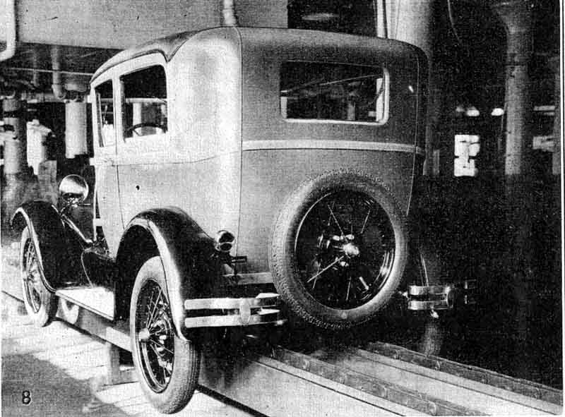
64. Assemble rear wheel and tire assembly to rear end of body, with three lugs, and tighten.
|
|
65. Assemble carburetor adjusting rod in place with spring, sleeve, collar, and two anti rattlers.
|
|
66. Assemble four license clips to head lamp support rod with two bolts, lock washers and nuts.
|
|
67. Assemble to inside of body, four rubber covers, twenty four tacks, two rubber pads.
|
|
68. Assemble hand brake lever assembly in place.
|
|
69. Assemble hood assembly.
|
|
|
70. Start engine and run off of assembly conveyor.
|
|
71. Final inspection.
|